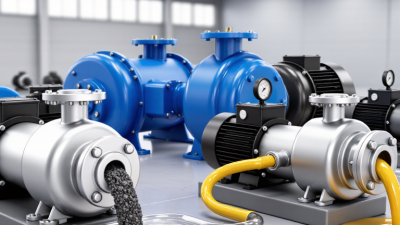
What Is a Double Diaphragm Pump and How Does It Work?

A double diaphragm pump moves liquid using two flexible diaphragms that work in alternating strokes. Compressed air, or another suitable drive system, shifts the diaphragms back and forth inside the pump body. This movement changes the volume of each chamber, drawing fluid through an inlet and pushing it toward an outlet. Check valves guide the flow in one direction.

The principle is straightforward. The details matter.

In an air-operated model, air pressure moves one diaphragm while a connecting shaft moves the other. As one chamber fills, the other discharges. Then the cycle reverses. The pump can handle many fluids, including some viscous liquids and fluids containing suspended solids, but suitability depends on materials, particle size, temperature, and operating conditions. “Self-priming” does not mean it can run dry indefinitely or overcome every installation problem.

This guide explains the main components, the pumping cycle, and common applications. It also considers practical factors such as diaphragm material, flow requirements, air supply, and maintenance access. These choices affect performance and service life. A pump may look simple on a diagram, yet a mismatched seal or poorly sized air line can cause real trouble. That is worth remembering. The right selection starts with the fluid and the job, not just the pump’s advertised capacity.
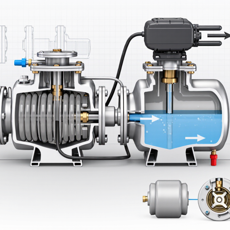
What Is a Double Diaphragm Pump and How Does It Work?

Definition and Core Components of a Double Diaphragm Pump

A double diaphragm pump is a positive-displacement pump that moves liquid using two flexible membranes. Compressed air or another drive source moves the diaphragms back and forth. One side draws liquid in while the other pushes it out. Then the flow switches. The cycle repeats.

Its core components include two diaphragms connected by a central shaft, an air-distribution valve, and a liquid-handling chamber. Inlet and outlet manifolds guide the fluid through the pump. Check valves, often ball or flap designs, open and close with pressure changes to control direction. The air valve alternately sends compressed air behind each diaphragm. This creates the movement without requiring a rotating impeller in the liquid path. Materials vary, so diaphragm and valve compatibility should be checked against the fluid and operating conditions. It is an easy detail to overlook.

Tips: Before installation, confirm the pump’s flow direction and check-valve orientation. Inspect diaphragms and seals regularly, especially if the pump handles abrasive or viscous liquids. Listen for unusual air leaks, but do not treat sound alone as a diagnosis. A pump may still run while a diaphragm is wearing. Proper maintenance intervals depend on duty cycle, pressure, and fluid properties.

How Two Diaphragms Create Alternating Suction and Discharge Strokes

A double diaphragm pump uses two flexible membranes to move liquid through separate pumping chambers. Compressed air pushes one diaphragm outward, reducing the chamber’s volume and forcing liquid toward the outlet. At the same time, a connecting shaft pulls the other diaphragm inward, creating suction that draws liquid through the inlet. The membranes do not touch each other. They separate the pumped fluid from the air mechanism.

Check valves control the direction of flow. During suction, an inlet valve opens while the outlet valve stays closed. During discharge, those positions reverse. Then an air-distribution valve shifts the pressure to the opposite side, and the cycle repeats. The two strokes alternate. That simple rhythm can handle liquids containing suspended particles, though the permitted particle size depends on the pump’s design.

In practice, flow is not perfectly smooth. It pulses, and the sound or vibration can become noticeable as operating conditions change. A discharge hose may twitch slightly. Air pressure, fluid viscosity, and worn valves can all affect performance. Operators should check the actual pressure and material limits rather than assume every double diaphragm pump behaves alike. A small mismatch can matter.

Air Distribution and Check Valves: How Fluid Flow Is Controlled

A double diaphragm pump moves liquid through two flexible diaphragms linked by a common shaft. Compressed air enters an air distribution valve, which directs it behind one diaphragm and then the other. As one diaphragm pushes fluid out, its partner draws fluid into the opposite chamber. The valve shifts when the diaphragms reach the end of their stroke. That timing matters.

Check valves control the liquid path, not the compressed air. At each chamber, an inlet valve opens when suction lowers the pressure; an outlet valve opens as the diaphragm pushes fluid forward. The valves usually use balls or flaps that lift from their seats, then close against reverse flow. Their simple action depends on clean seating surfaces and suitable fluid conditions. A worn seat, sticky ball, or trapped debris can cause backflow or uneven delivery. Still, not every uneven pulse points to a faulty valve; restricted suction or inconsistent air pressure can produce similar symptoms.

Tips: Watch the inlet and outlet connections while the pump runs. Unexpected pulsing or weak flow can be a clue, not a diagnosis. Check air pressure, suction restrictions, and valve condition before changing parts. Small details matter.

Double Diaphragm Pump: Air Distribution and Check-Valve States

Simplified operating sequence: the air distribution valve sends compressed air to one diaphragm while exhausting the other. The pressurized chamber’s outlet check valve opens to discharge fluid; the opposite chamber’s inlet check valve opens to refill. The states switch when the diaphragms reach the end of their strokes. Actual valve timing varies by pump design and operating conditions.

Typical AODD Ratings: Up to 8.6 bar Air Pressure on Some Models

What Is a Double Diaphragm Pump and How Does It Work?

A double diaphragm pump uses compressed air to move two flexible diaphragms back and forth. As one chamber draws in liquid, the other pushes it through an outlet check valve. The valves help control flow, while the air drive keeps the liquid separate from the compressed air. This makes the design useful for transferring fluids with changing viscosity or small amounts of suspended solids.

Some air-operated double-diaphragm (AODD) models are rated for air pressure up to 8.6 bar, or about 125 psi. That figure is a model-specific maximum, not a recommended setting for every installation. In many AODD designs, discharge pressure can approach the air-supply pressure, but hose losses, fluid lift, and backpressure affect actual performance. The U.S. Department of Energy’s Improving Compressed Air System Performance sourcebook notes that leaks can waste 20–30% of compressor output in poorly maintained systems. A high pump rating cannot make up for an undersized or leaking air line.

Tips: Check the pump’s pressure curve and maximum air-inlet rating before operation. Measure pressure at the pump while it is running; a static gauge reading can be misleading. A rating is not a promise of steady flow. That distinction is easy to miss.

Large-Pump Capacity: Some 3-Inch Models Exceed 1,000 L/min

A double diaphragm pump uses compressed air to move two flexible diaphragms back and forth. Their alternating strokes draw liquid through an inlet and push it out through an outlet, while check valves control direction. There is no rotating impeller in the liquid path. That makes the design useful for transferring slurries or liquids containing suspended solids, provided the pump’s materials and valve clearances suit the fluid.

Capacity is the striking figure for larger models. Published technical specifications for some 3-inch air-operated diaphragm pumps list maximum flow above 1,000 L/min, or about 264 gallons per minute. At that theoretical rate, a 200-liter drum would fill in roughly 12 seconds. In real installations, flow falls with thicker liquids, long or narrow hoses, suction lift, and backpressure. I would treat the maximum rating cautiously; it is not a promise of steady site performance. Check the pump curve against the actual fluid and piping.

Air supply matters, too. The U.S. Department of Energy’s Improving Pumping System Performance sourcebook reports that pumping systems account for nearly 20% of global electricity demand, underscoring why operating conditions deserve attention. An air-driven pump still consumes energy through its compressed-air supply. Measure air pressure and flow at the pump, not just at the compressor. A small pressure drop can change output more than expected. That detail is easy to miss.